Today I need a ± 100V symmetric power supply for a few mA of current consumption. I have this power supply from my broken audio amplifier, which can deliver ± 40V or ± 50V DC peak, depending on the 4/8 Ω switch for the transformator taps. Can I double the voltage somehow?
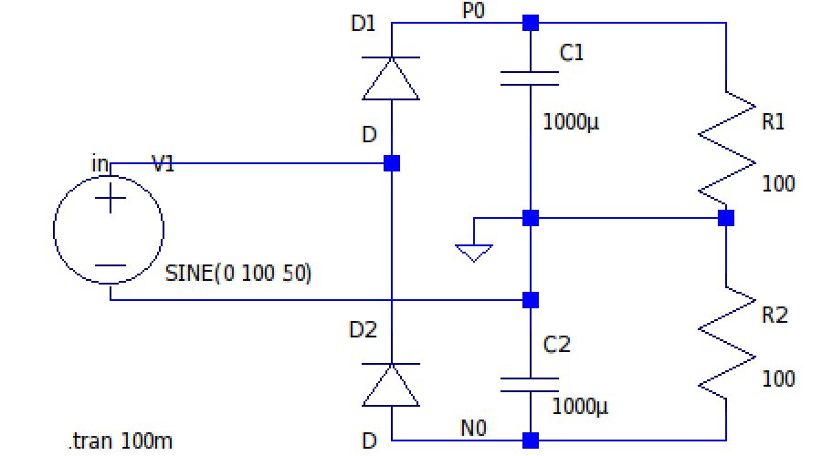
There is an interesting circuit called Delon voltage doubler (Wikipedia), which promises exactly what I am looking for. Jules Delon (1876-1941) was a French engineer, who presented his device in 1908 in Marseille, using mechanical switches at that time. The idea is to combine two half-wave rectifiers (aka peak detectors) on top of each other, so that both capacitors can load to the peak voltage. Their voltages add together, as a quick simulation with LT Spice shows. The resistors simulate load.
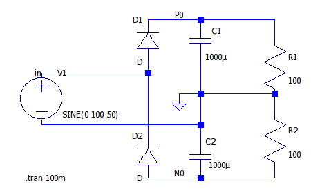
With my symmetric transformer I just ignore the middle tap. The diodes have to withstand 200V, capacitors 100V. Delon doubler can provide quite some current, same as a half-wave rectifier - there is no charge pump involved. The same dimensioning rules as for a half-wave rectifier apply, say 1000 μF per 1A of current for 20% peak drop. Here with 1000 μF it provides 0.9A of mean current at ca. ± 90V mean value.
Increasing the voltage comes with a price, there are energy losses involved and mean current will increase more than twice. Factor 2 is just an ideal value.

Delon doubler is a different circuit than a Villard or Cockcroft-Walton cascade multiplier, which needs 3 or 4 capacitors and 4 diodes to double the input voltage. Delon circuit cannot be cascaded, but see below.
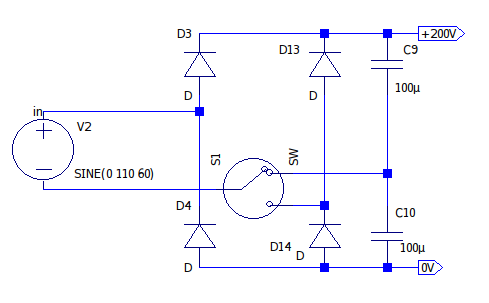
A 110V / 230 V switch on a PC power supply changes between a bridge rectifier and Delon doubler topology (Wikipedia), so that the switched power supply is provided with roughly the same, high input DC voltage. The transformer saturation current can be lowered, saving costs. Very clever.
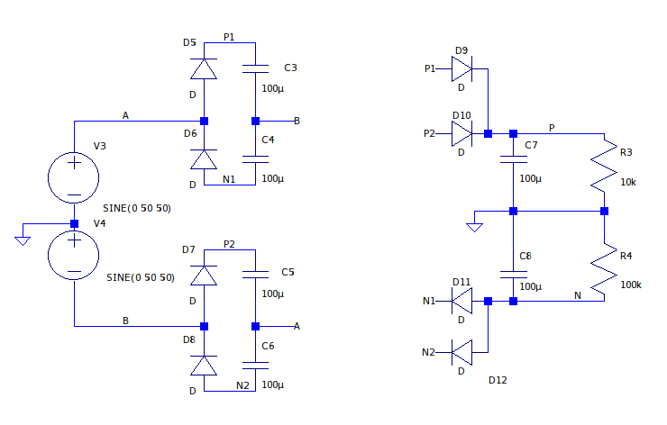
But what if I put a Delon doubler on each transformer output and try to combine these? That is a voltage trippler and the ripple is now 2 × f = 100 Hz. Each doubler gets 100V AC and produces ± 100V DC ± 50V AC, ± 150V DC peak. Cool, but it is more than I need.

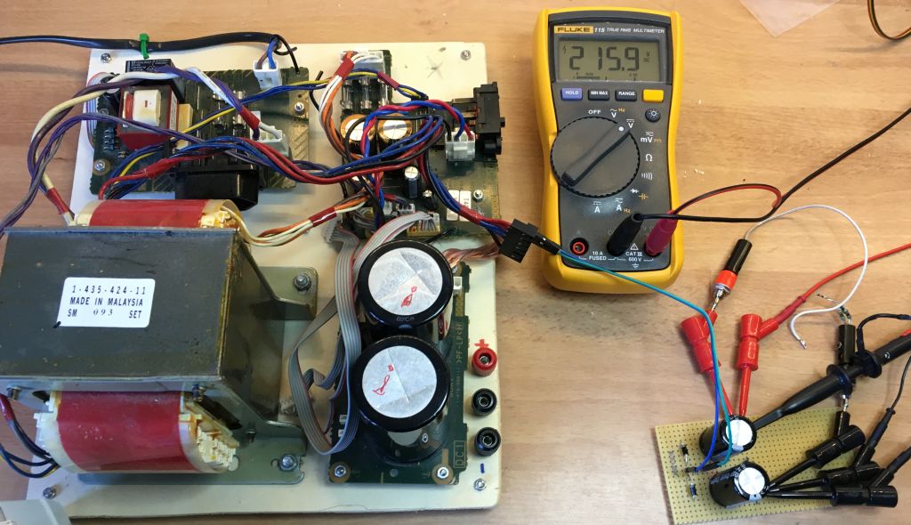
Coming back to my original problem, I built up the original version of Delon doubler with 2 × 1N4007 diodes and 2 × 100 μF @ 400V capacitors, more than sufficient for my low current. I measured ± 80V and ± 108V with 5 kΩ load, which got so hot, that it unsoldered itself. I was not quick enough...
Caution, high voltage !!!
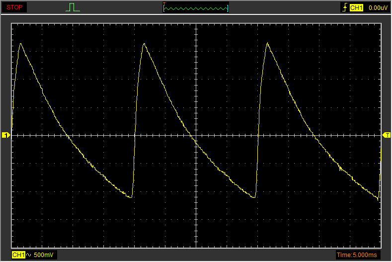
The ripple over single output voltage is f:
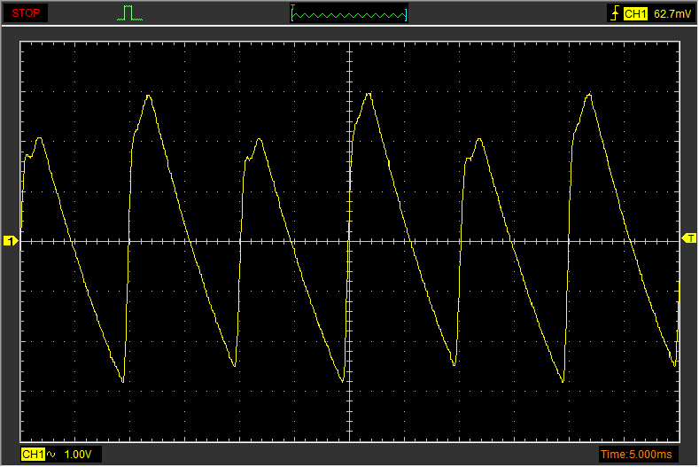
Ripple over both output voltages is 2 × f. The capacitors are probably not equally good:
Inspired by the PC PSU trick, I added a second pair of diodes, so now I can also use this board as a bridge (connecting also the middle tap), getting switchable ±40, 50, 80 or 100V. The original 15 mF capacitors are just too big for my test circuit, taking hours or a resistor to discharge.
A diode bridge is often named a Graetz bridge, after Leo Graetz (1856 Breslau - 1941 Munich), a Jewish German physicist, but it was patented before him by a Polish inventor Karol Pollak (1859 Sanok - 1928 Biała).
