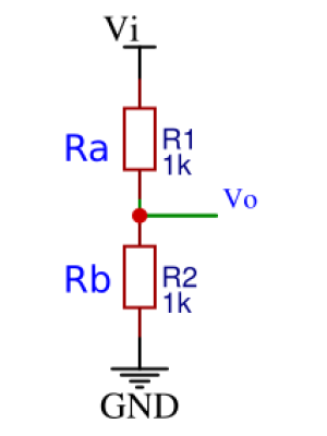
In electronics there is hardly anything simpler than a voltage divider circuit. Most people know that Vo = R2 / (R1 + R2) * Vi, where R2 / (R1 + R2) = f is the divider fraction. But it is not obvious how to choose the resistor values. You can start with one value, calculate the other one, get some error, try to find improvement... Or use a web-based tool like TI Voltage Divider Calculator. Say I need a fraction of 0.1:
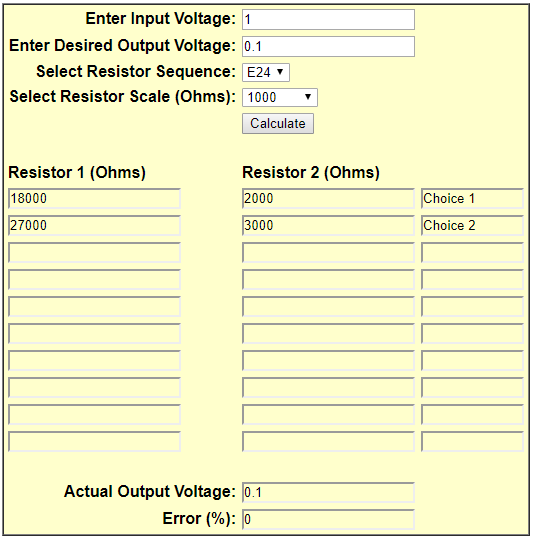
Hmm, I do have 18k and 2k resistors at hand, the choice is right, but not intuitive. How does this calculator work? What is behind E24? What about tolerances? What happens under load? Do I really need a special calculator at all?
Similar questions appear when dealing with:
- capacitive and inductive dividers
- adjustable LDOs
- current dividers
- RC, LC filters
- opamp circuits and active filters
Calculators
Mark Biegert has written a very fine article about Optimum Resistor Ratio Approximation Using Standard Components in his Maths Encounter Blog aka mathscinotes.com.
He solved the problem using brute force search, implemented in MathCAD and Excel. The number of combinations is limited to a few hundred, up to few thousand. No sweat for a modern PC to try all of them out. E24 has 24 values, they make 24 * 24 = 576 combinations. E96 with 96 * 96 throws out 9216 combinations. Many make little sense to try, but nothing is left out. Mark has put up several test cases and found some improvements over Bennet's Resistor Ratio Calculator he's been using so far. The point here is, with ample computing power in our hands, a simple approach saves a lot of human effort. The PC is running idle most of the time anyhow. This is how these calculators work.
Mark greets us with his Quote of the Day, well worth repeating:
Being defeated is often a temporary condition. Giving up is what makes it permanent.
— Marilyn vos Savant
I do not feel defeated by resistor dividers yet. There is another way to look at it - the problem at hand is defeated, but why give it up?
E12, E24 and so on
Nowadays we can cheaply buy resistors from 0.1 Ohm up to 10 Mega Ohm - 8 decades. Capacitors go from 1 pF to 10 F - these are proud 13 decades. Decade is not just 10 (like in 10 years), it is every time 10 times more. The physical money we know, 1 cent up to 1000 spans just 5 decades. Still we can spend billions on weapons and such, but that's another issue.
What's perhaps more interesting: in order to deal with these enormous dynamic ranges biological creatures have developed logarithmic senses. Thanks to these two German gentlemen, Prof. Weber und Prof. Fechner, looking like hippies of the XIX century, we understand that we hear in dB and spend money in dB. Look into your purse and consider the spending effort. 1 ct to 1€ feels very much the same step like 1 € to 10 € - provided you have the money.
In the early days of industrial resistor and capacitor production some clever people had the great idea to use geometric series to cover this enormous range of possible values. This is now called E-series like E12, E24 and so on. The basic idea is to cover each decade with N identical steps, where N = 3, 6, 12, 24, 48, 96. This corresponds to the geometric series with a quotient q = 10 ** (1/N). I will be using Python in this post, so ** is the power operator. In Matlab and Octave a hat ^, which C-like languages use for xor.
In other words the quotient is the N-th root of 10. The quotients for E6, E12, E24, E48 and E96 are:
q06 = 10 ** (1/ 6) = 1.467799 or ca. 40% apart, 20% tolerance
q12 = 10 ** (1/12) = 1.211528 or ca. 20% apart, 10% tolerance
q24 = 10 ** (1/24) = 1.100694 or ca. 10% apart,  5% tolerance
q48 = 10 ** (1/48) = 1.049140 or ca.  5% apart,  2% tolerance
q96 = 10 ** (1/96) = 1.024275 or ca.  2% apart,  1% tolerance
so the number of steps is chosen to give the right step size in percent and doubles at every refinement.
E12 is just every second value of E24, E6 and E3 are further decimations. The values are the same. Most capacitors are E12, inductors perhaps E6? Nowadays E12 and E24 are often available as 1% and 2% values, both THT and SMD, and since I hardly have any E96's in my drawer, I will concentrate on E24 now. Also q24 = 1.1 is easy to remember.
E6, E12 and E24 are rounded to 1 decimal place after comma, E48 and finer use 2 decimal places. I wrote a quick Python script to calculate the E24 values:
# Calculate E-series
import numpy as np
N = 24 # E-series to calculate
digits_after_comma = 1
q = 10**(1/N)
print("E%d q = %.6f" % (N, q))
n = np.arange(0, N+1) # include 10
vals0 = q ** n
vals = np.round(vals0, digits_after_comma)
print(vals)
E24 q = 1.100694
[ 1. 1.1 1.2 1.3 1.5 1.6 1.8 2. 2.2 2.4 2.6 2.9 3.2 3.5 3.8
4.2 4.6 5.1 5.6 6.2 6.8 7.5 8.3 9.1 10. ]Something is wrong here! Most electronics afficionados would know numbers like 2.5, 2.7, 3.0, 3.3, 3.6, 3.9, 4.3, 4.7 and 8.2 by heart. But these here are off by 0.1 this way or another. Wikipedia speaks of "unknown historical reasons". I have a few hypotheses:
- A computer, which I imagine as a hall full of ladies in 1940' clothes, made a mistake. Taking 24th-degree root with just pen and paper is tough. But there were function tables and the result is not so difficult to verify. Unlikely.
- Somebody in Manhattan Project needed these values for their voltage dividers, so general X made a call to Resistors, Inc. "I need these 3k resistors ASAP! A matter of national security!". Unlikely, you can always add 100 Ohm in series.
- The boss at Resistors, Inc. suffered from numberophobia and didn't like some numbers. Unlikely - he had to see many numbers.
- Mr. X, a crazy scientist at Resistors, Inc. wanted to give us more options for resistor dividers. This would be cool, but is not the case, as we will see later.
- Mr. X convinced everybody that the increments need to be consistent. This is the most probable cause.
Here is the corrected E24 series as we know it, together with the increments (deltas). E12 values, more common, are at even indices. I will write e23 to mean 9.1, as in 91 Ohm, 9.1k, and 910k - the decades are flexible.
| index | 0 | 1 | 2 | 3 | 4 | 5 | 6 | 7 | 8 | 9 | 10 | 11 | 12 | 13 | 14 | 15 | 16 | 17 | 18 | 19 | 20 | 21 | 22 | 23 | 24 |
|---|---|---|---|---|---|---|---|---|---|---|---|---|---|---|---|---|---|---|---|---|---|---|---|---|---|
| value | 1.0 | 1.1 | 1.2 | 1.3 | 1.5 | 1.6 | 1.8 | 2.0 | 2.2 | 2.4 | 2.7 | 3.0 | 3.3 | 3.6 | 3.9 | 4.3 | 4.7 | 5.1 | 5.6 | 6.2 | 6.8 | 7.5 | 8.2 | 9.1 | 10 |
| delta | 0.1 | 0.2 | 0.3 | 0.4 | 0.6 | 0.7 | 0.9 |
This table covers perhaps 99.9 % of the world's passive electronic elements (resistors, capacitors, inductors).
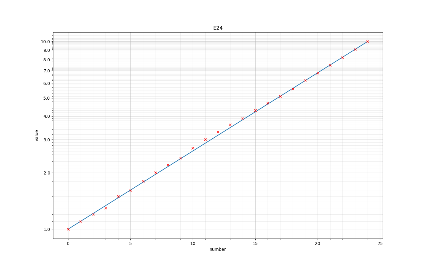
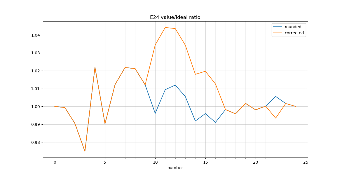
It is interesting to look at the E24 series on a semilogarithmic plot. The discrepancies due to rounding are stronger in the beginning. Mr. X's correction is visible in the middle, even more if the ratio to the ideal value is plotted. The discrepancies are not big, -2 .. +5%.
In case you wondered why we have 1.6A fuses or 630V capacitors, there is a similar, but older creation called Renard series taking 5, 10 or 20 steps pro decade. Colonel Charles Renard was XIX century French inventor. Frustrated by the lack of funding and refusal from the French Académie des sciences he commited suicide in 1905, so please remember him when choosing a fuse or capacitor.
Voltage Divider revisited
The fraction f = R2 / (R1 + R2) = 1 / (R1 / R2 + 1) of the divider depends solely on the ratio of the resistor (or inductor) values r = R1 / R2 or r = L1 / L2. For capacitors the ratio would be r = C2 / C1 because the impedance is Xc = 1 / (j*w*C), inverse proportional of capacity. I will stick to resistors first. Because these values are from E24 geometric series, we can write them as R1 = q ** a, R2 = q ** b, where a, b - integers. So the ratio r = R1 / R2 = q ** a / q ** b = q ** (a - b) is also a value from E24 series you and I know well already and it depends mostly on the E24 shift a - b between R1 and R2.
The quick way to find the resistor values for the voltage divider:
- calculate the ratio from fraction
r = 1 / f - 1. For my examplef = 0.1, r = 9. Easy to remember and for the calculator. - choose the ratio value from E24. Here e23 = 9.1
- Use R1 = r, R2 = 1 if good enough. For example 9.1k / 1k or 910 Ohm / 100 Ohm (10 % too low).
- Otherwise try to improve by shifting to the left or right along E24 table. For example 10k / 1.1k and so on. You need some patience to come accross 18k / 2k or 27k / 3k, which are perfect.
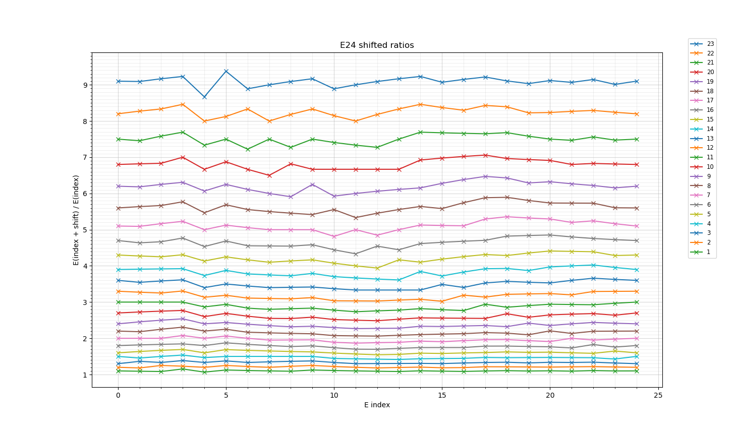
I plotted the ratios R1 / R2 vs. E24 index of R2 and shift. You can spot 9.0 at shift 23, index 7 (e7 = 2.0) or 11 (e11 = 3.0). Instead of taking right shift of 23 you can go left by 1 and multiply by 10 to get 18k and 27k. The zigzack in the plot is due to rounding errors when values are small. Mr. X's correction is visible as a flat hill. Without rounding and correction, these lines would all be flat. We would have 23 almost equivalent choices for any resistor divider - in this case all off by 10%. Not good.
I implemented the global search (brute force) for the optimum value. Doesn't handle multiple optima for one shift, but it is not a big issue.
Searching for fraction 0.100000, ratio 9.000000
index 7 shift 23: R1 18.000000 R2 2.000000 value 9.000000 delta 0.000000
BTW there is no way to build a 1:10 divider using just two E12 values.
More examples? Say I need 3.3V configuration for a LM317. Most adjustable regulators follow something like Vout = Vref * (1 + R1/R2) + Iadj * R1. Here Vref = 1.25V, Iadj = 50uA and I swapped R1 and R2 from the datasheet to fit my convention (R2 at Vref). Omitting Iadj first I get the ratio = 1.64. I could take R1 = e5 = 1.6k, R2 = e0 = 1k, this gives Vout = 3.33V, which should be fine.
E24 as a logarithmic slide rule
My father has taught me once how to use a logarithmic slide rule, aka slipstick. E24 can also be used as a crude one (few %).
This brings us all the way back to Edinburgh, Scottland, around 1610, when John Napier invented logarithms and found out that multiplication and division can be mapped to simpler addition and subtraction. Ohm's law is all about multiplication and division, and with E24 this is just walking up and down the table. Completely pen and paper. It works also on a lonely island with finger and sand, so preppers, please pay attention. Even if there is no electric current on a lonely island, you can still use it to calculate the daily rations or survival chances.
Let's say we need a resistor to draw 1.8 mA from 3.3V. I like to do Ohm's law in V, mA and kOhm. R = V / I = e12 / e6 = e6 = 1.8 k. The true value is 1.83. E24 tells us a square root of 3.3 is around 1.8, and these values are good to remember: e6 = 1.8, e12 = 3.3 and e18 = 5.6. 50 uA * 1.6 k in example above is e(17 + 5) = e22 = 82 mV. It needs some caution to get the decade right.
Conductivities, G = 1 / R = q ** (-a) are also E24 values. 1 / 4.7 ~ 2.2, 1 / 7.5 ~ 1.3. So the same approach is also useful for a current divider.
Say you need a RC time constant of 50 us. If R = q ** a and C = q ** b the time constant tau = q ** (a + b) is also a E24 value. You can choose tau = e17 = 51 us, C = e0 = 1nF, R = e17 = 5.1k. Or C = e8 = 22 nF, R = e9 = 2.4 k, tau = 52.8 us. Or C = e16 = 47 nF, R = e1 = 1.1 k, tau = 51.7 us. You can use E12 values for capacitors and E24 values for resistors to get more flexibility.
I need an amplifier A = 20. In non-inverting configuration this calls for ratio 19, R1 = 82k : R2 = 4.3k says the calculator. Probably that's why people would rather use an inverting amplifier with something like 200 k : 10k or live with A = 21. Now I want to limit the bandwith to fc = 20 kHz with C || R1. The impedance of C at fc will match R1 or
# R1 = 1 / (w*C), w = 2 * pi * fc
C = 1/(2 * pi * fc * R1)
# 2 * pi ~ 6.28 ~ e19, fc = 20k ~ e7 * 1e4,  R1 = 200k ~ e7 * 1e5
C = 1nF / e(19 + 7 + 7) = 1 nF / e(-33) = 100 pF / e(-9) = e15 * 100 pF = 430 pF
The accurate value is 398 pF. I would rather use a calculator or interactive REPL in Python or Ruby and choose 390 pF.
Series and parallel connections are more complicated with the log scale - addition becomes difficult. We can use them to obtain values outside of E24 series.
R1 + R2 = q ** a + q ** b = q ** a * (1 + q ** (b -a))
R1 || R2 = R1 * R2 / (R1 + R2) = q ** (a + b) / (q ** a + q ** b) = q ** a / (1 + q ** (a - b))
This means that if a and b are far apart you can drop the much lower value (in series) or higher value (in parallel), but you already knew that. It is easy to imagine the series connection as a mechanical rule - it is a linear one. I would like to have such a rule for the parallel connection.
Further thoughts
- Our sense of the world is logarithmic, and it helps to calculate in log units, like E24
- You can download my e24.py Python script. It needs numpy, matplotlib and PyQt5. I could clean it up towards a reusable tool.
- It would be cool to build a physical or perhaps better a virtual slide rule to calculate E24 ratios and products
- I could write more about the tolerance of the result and the load effects on the voltage divider